V Voltmeter Wiring Diagram
V Voltmeter Wiring Diagram. Different types of voltmeters include analog voltmeters with moving coil instruments, VTVMs and FET Voltmeters and digital voltmeters with A/D converters. It shows the components of the circuit as simplified shapes, and the facility and signal contacts with the devices.
See more ideas about Diagram, Electrical wiring diagram, House wiring.
This pictorial diagram shows us the.

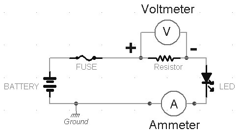
LED Digital Voltmeter Working with Circuit Diagram

Circuit diagram, ammeter, voltmeter - YouTube
Dc Ammeter Shunt Wiring Diagram

Digital Arduino Voltmeter 0V-12V-30V

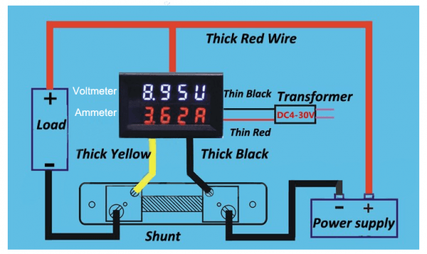
Digital Volt And Amp Meter Circuit Diagram
Ammeter - wikidoc

Autometer Oil Pressure Gauge Wiring Diagram | Free Wiring ...
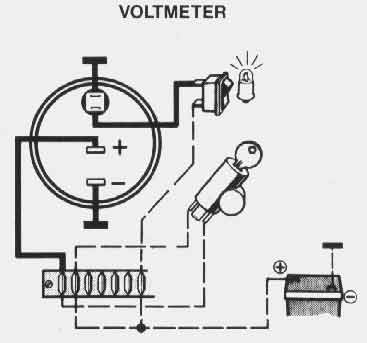
VDO Performance Instruments
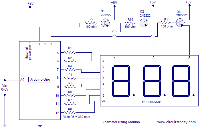
Simple 0-5V three digit voltmeter using arduino. 50mV ...
Voltmeter Gauge Wiring Diagram- wiring diagram is a simplified customary pictorial representation of an electrical circuit. Before using a voltmeter for the first time, learn how to set the device correctly, and test it out on a low-voltage circuit such as a. I know the small red and black go to power source.

0 Response to "V Voltmeter Wiring Diagram"
Post a Comment