V Trolling Motor Wiring Diagram Picture
V Trolling Motor Wiring Diagram Picture. Now you are ready to properly attach your trolling motor to your batteries. Trolling motor wiring overview by Newport Vessels for Newport Vessels trolling motors.

Low Voltage Release and Low Voltage Protection are the basic control circuits encountered in motor control applications.
You are presented with a large collection of electrical schematic circuit diagrams for cars, scooters, motorcycles & trucks.

Minn Kota 5 Speed Switch 2884026 | Northland Marine
Trolling motor fuse placement - The Hull Truth - Boating ...
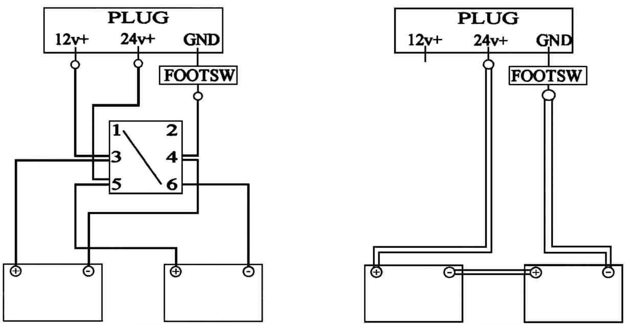
Minn Kota 24v Wiring Diagram

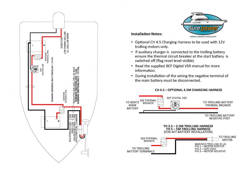
36 Volt Trolling Batteries Installation and Wiring - YouTube

Minn Kota 5 Speed Switch 2064028 | Northland Marine
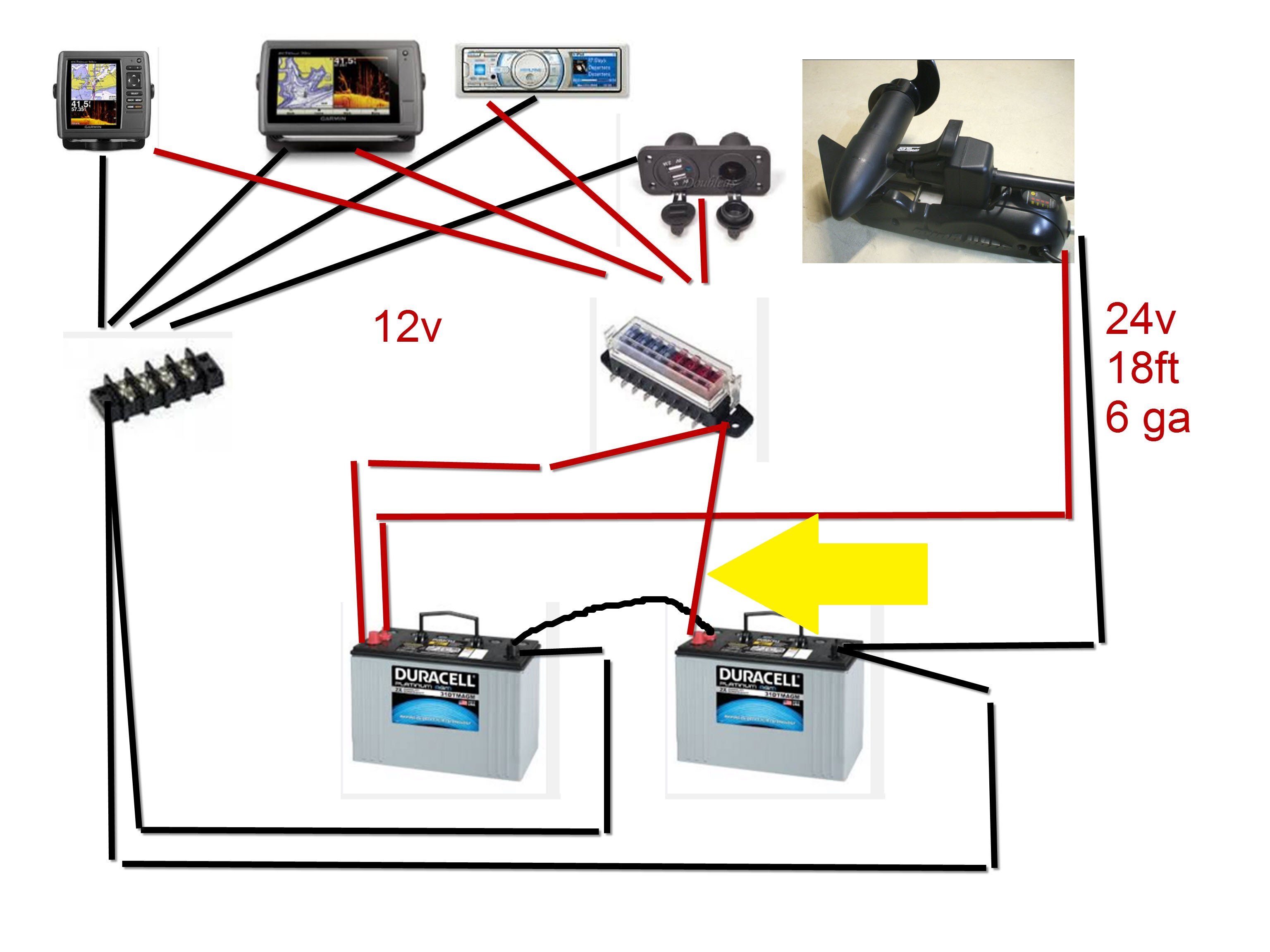
Your thoughts on this trolling motor accessories wiring ...

Minn Kota® 60 Amp Circuit Breaker - TrollingMotors.net
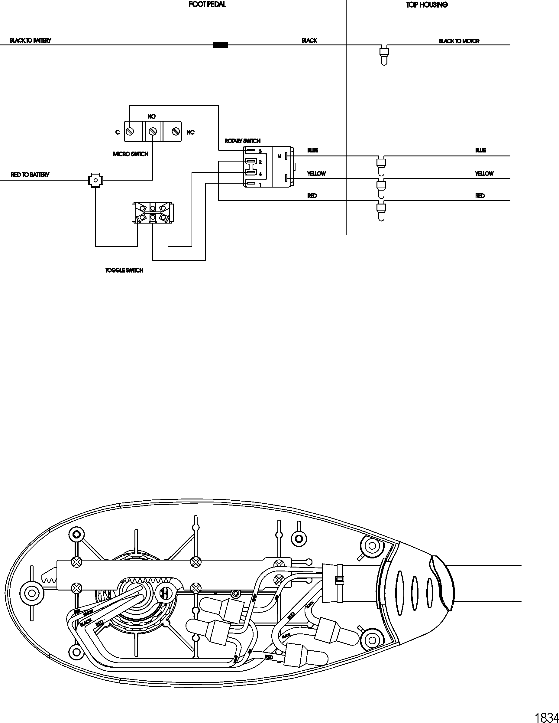
Wiring Diagram Motorguide Trolling Motor
Minnkota Autopilot 24 Volt Plug Wiring Diagram
Take the red (positive) wires and attach it to the positive. Motor - A Motor represents a transducer by which electrical energy gets converted to kinetic energy. On the head of the unit (where the direction indicator is) push down and turn the round plastic plate (this plate has the direction indicator on it) clockwise until.

0 Response to "V Trolling Motor Wiring Diagram Picture"
Post a Comment