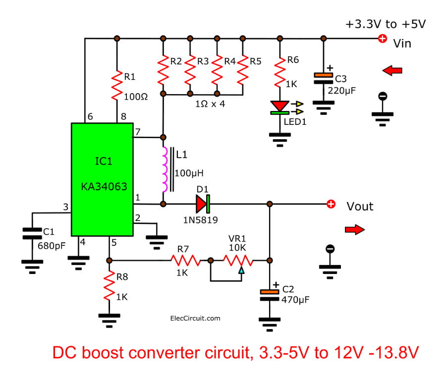
V Dc Schematic Wiring Diagram
V Dc Schematic Wiring Diagram. Wiring diagrams are made up of two things: symbols that represent the components in the circuit, and lines that represent the connections between them. Structure F : Flux Free Type S : Washable Type.
For example, how the horns are powered and connected to the controller on your steering wheel.
Free electronics schematic diagrams downloads, electronics CAD software, electronics circuit and wiring diagrams, guitar wiring diagrams, tube amplifier schematics, electronics repair manuals, amplifier layout diagrams,PCB software for making printed circuit boards, amplifier design software.
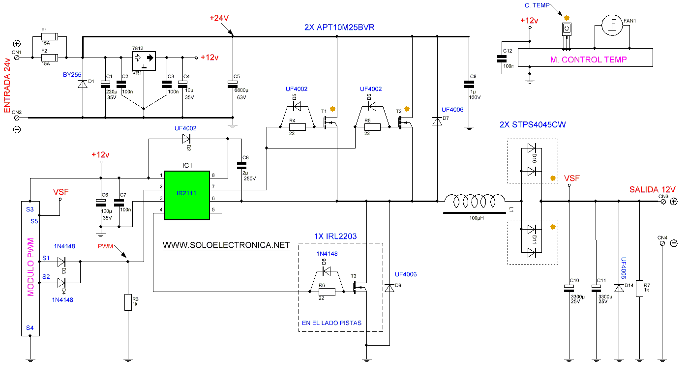
24V to 12V 400W DC Inverter

Speed Control of DC Motor Using Pulse Width Modulation, 555
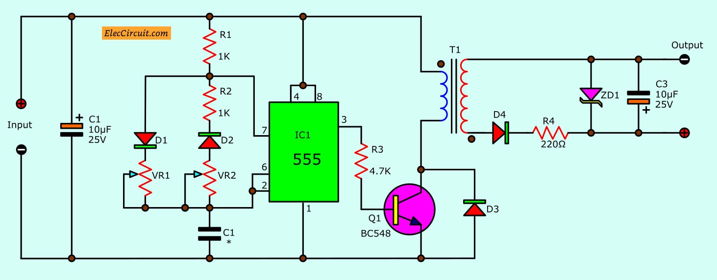
Isolated DC Converter for Digital using 555 | ElecCircuit.com
555 PWM LED dimmer circuit diagram | Power Battery Saving ...

DC Refrigeration :: Nova Kool Support :: Nova Kool DC ...

Simple Dc Ac Inverter Wiring diagram Schematic | Panel ...

LTC3440 5V Boost Converter Circuit ~Circuit diagram
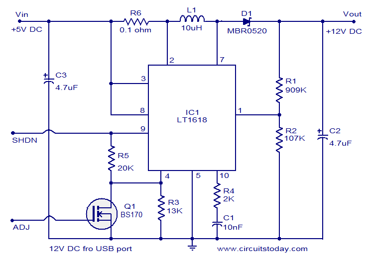
12 Volts DC Power Supply from USB port
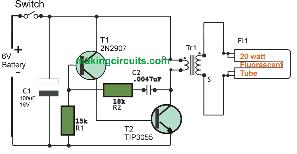
6v DC 20 watt Florescent Lamp Driver Circuit
Customize hundreds of electrical symbols and quickly drop them into your. F ELECTRICAL WIRING DIAGRAM (System Circuits). A wiring diagram is a type of schematic that uses abstract pictorial symbols to show all the interconnections of components in a system.

0 Response to "V Dc Schematic Wiring Diagram"
Post a Comment