V Diode Relay Wiring Diagram
V Diode Relay Wiring Diagram. A positive and negative voltage can be placed on either end. I-V (current vs. voltage) characteristics of a p-n junction diode.

These diagrams show all the wiring between each fuse in the Fuse Boxes and the components connected to These diagrams also aid in troubleshooting an inoperative circuit by showing a second circuit Damage to these devices may result.
CT operated relay triggiring block diagram with circuit for final triggring circuit.
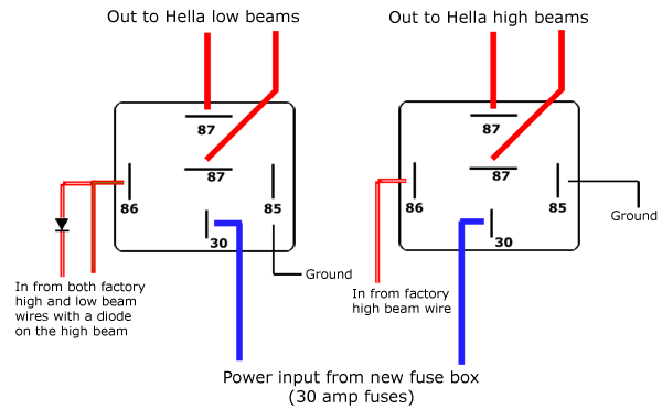
Headlight relays - SterlingKitCars.com

LDR Circuit Diagram
Report Manual: Relay Wiring Diagram - Bosch (Diagram Ebook)
Relay Isolator vs. Diode Isolator - YouTube
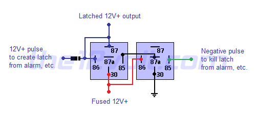
Latched On/Off Output Using Two Momentary Pulses, 1 ...
Bosch 5 Pin Relay Wiring Diagram - Allove - Relay Wiring ...
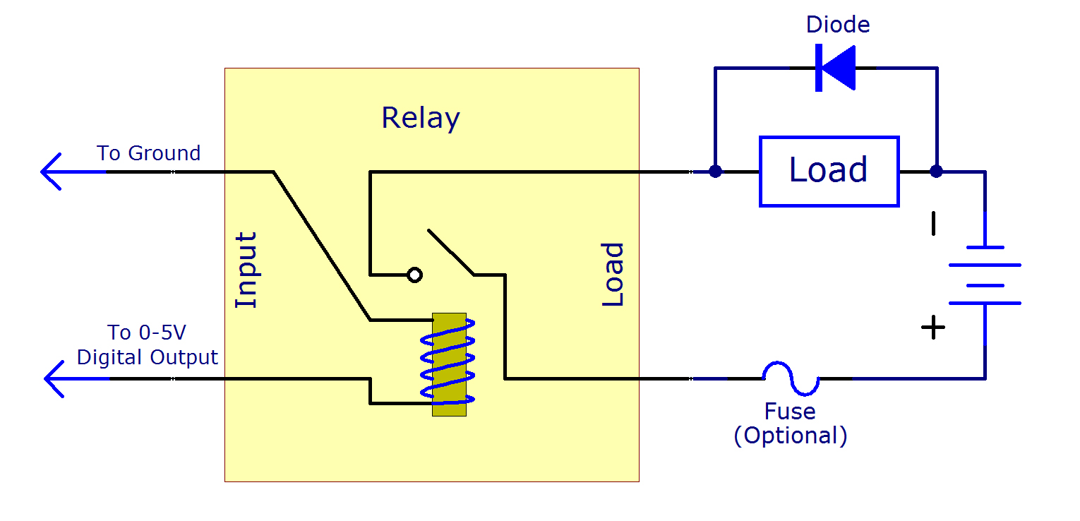
Mechanical Relay Primer - Phidgets Legacy Support
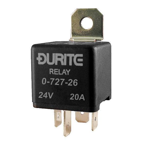
Durite 24V 20A Make and Break Car Relay with Diode | Re: 0 ...
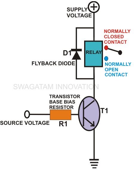
How to Wire a Relay to a Transistor - Explained through ...
Internal circuit diagram of relay driver ic Darlington pairs is given below. What is a Relay and How Does it Work? I was going to wire it up yesterday but mention of reverse diodes, physical relay separation and shielded cable made me doubt I was doing things correctly!

0 Response to "V Diode Relay Wiring Diagram"
Post a Comment