V Timer Switch Wiring Diagram
V Timer Switch Wiring Diagram. They are basically the wire nuts you see in the lower left of the lower image. Power supply voltage rating Power consumption (MAX) Display type.

Study each symbol so you can identify them by sight.
You can watch the following video or read the written tutorial below.

120 Volt Relay Wiring Diagram Download

Simple Delay Timer Circuits Explained

I have a Intermatic ET70215C i am trying to run 2 240 volt ...
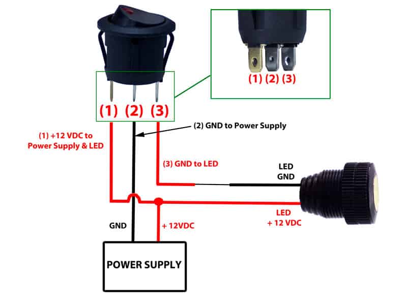
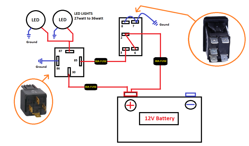
Dorman 84944 8 Pin Rocker Switch 12 Volt Wiring Diagram
New LED Rocker switch help! - Jeep Cherokee Forum
MZL-26 12v Ignition Sensing Delay Timer | ACDC Industries
Dorman 84944 8 Pin Rocker Switch 12 Volt Wiring Diagram

Ignition Switch 5 Wire Start 110cc 125cc 150cc 250cc Quad ...

Digital Stop Watch - Simple Projects
They are also useful for making repairs. There is a "wiring diagram" and adjacent to it a "line diagram." TRl is an "on-delay" timer used for surge protection on starting. Example shows removal of break-away fin.

0 Response to "V Timer Switch Wiring Diagram"
Post a Comment