V Series Wiring Diagram
V Series Wiring Diagram. This pictorial diagram shows us the. Wiring diagrams show how the wires are connected and where they should located in the actual device, as well as the physical connections between all A resistor will be represented with a series of squiggles symbolizing the restriction of current flow.

An antenna is a straight line with three small lines.
A series circuit is a circuit in which components. earth points. wire lines (with reference).

Programmable Touchscreen Thermostats | Optimum Underfloor ...

Freightliner Trailer Plug Wiring | schematic and wiring ...
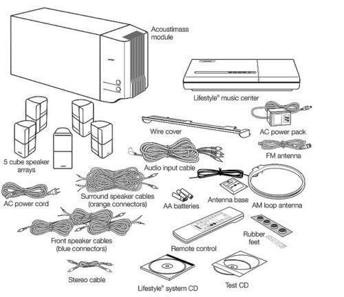
Bose Acoustimass 5 Series Ii Wiring Diagram

2006 Bmw 525i Engine Diagram

Bmw E39 Wiring Diagram Pdf

Bose Acoustimass 5 Series Ii Wiring Diagram | Free Wiring ...
Xp Battery Charger Wiring Diagram - Wiring Diagram Schemas

Repair Guides

TRUCK 5 TON M939 SERIES DIESEL SERVICE MANUAL - Auto ...
However, if you permanently wire the humbucker for series or parallel, you are. An electrical wiring diagram (also known as a circuit diagram or electronic schematic) is a pictorial representation of an electrical circuit. Wiring diagrams show how the wires are connected and where they should located in the actual device, as well as the physical connections between all A resistor will be represented with a series of squiggles symbolizing the restriction of current flow.

0 Response to "V Series Wiring Diagram"
Post a Comment