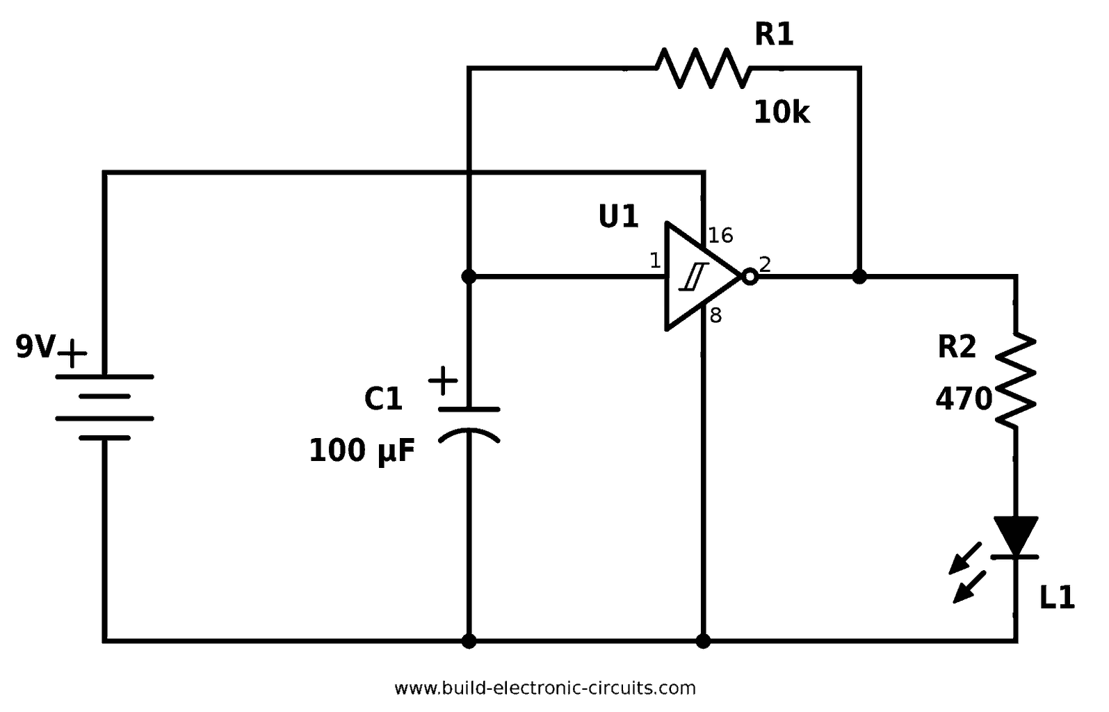
V Lamp Flasher Circuit Diagram
V Lamp Flasher Circuit Diagram. An LED flasher circuit is a circuit which flashes the LED- meaning turns it ON-OFF, ON-OFF, ON-OFF. This is a very simple lamp flasher circuit that uses only three components (a capacitor, relay and one resistor) other than the lamp.
Visit my Website for Buying Links & more Information about LED Flasher Circuit.
Here is the circuit diagram of Two Flashing LED's for different applications (such as model construction), and recreational.

FREE CIRCUIT DIAGRAMS 4U: 12V LED Flasher for Cars

Image result for 6 volt motorcycle blinker wiring diagram ...
_schematic.jpg)
Indicator Kits (without Lamps)
LED 깜빡이는 회로도

MadLab Electronic Kits - Flashing Lights

Wiring Diagram For 5 Pin Relay For Drl With Turn Signal Wire

CF13JL-02 LED Bulb Electronic Flasher | Car Bulb ...

LED Flasher Circuit Diagram with 555 | How to Make ...
How to build Adjustable Strobe Light (circuit diagram)
Alternatively, it can act as a bicycle light (subject to traffic. A bulb flasher circuit is very common circuit which most of us come across from time to time. An LED flasher circuit is a circuit which flashes the LED- meaning turns it ON-OFF, ON-OFF, ON-OFF.

0 Response to "V Lamp Flasher Circuit Diagram"
Post a Comment