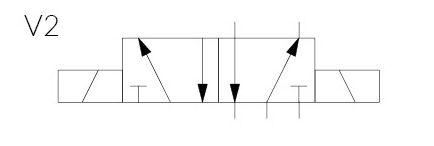
V Hydraulic Solenoid Valve Wiring Diagram
V Hydraulic Solenoid Valve Wiring Diagram. Solenoid valves are electromechanically operated valves and are used to control the rate of flow in fluid or air powered systems and are quite often just Solenoid valves are most commonly found in fluidics, fluid power pneumatic and hydraulic systems. No seals on sliding surfaces eliminates Refer to below diagrams for wiring from power source to conduit box and DIN connectors.

The one where I wire up the solenoid valve so that I can use it with a prop.
Tests carried out with solenoids at their working temperature.
Solenoid valves are control units which, when electrically energized or de-energized, either shut off or allow fluid flow. Drawing for Electric Hydraulic Power Unit Design. Fluid power diagrams and schematics require an independent review because they use a unique set of symbols and conventions.


0 Response to "V Hydraulic Solenoid Valve Wiring Diagram"
Post a Comment