V Led Indicator Light Wiring Diagram
V Led Indicator Light Wiring Diagram. Modern LEDs are bright enough at low current to use as directly mains powered indicators with minimal circuitry. The LED as a polarity indicator circuit is show in above diagram.
However, if you have electric brakes or.
LED (LIGHT EMITTING DIODE) Upon current flow, these diodes emit light without producing the heat of Location Malfunction Indicator Lamp (Check Engine Warning Light) [Telltale Light LH] Telltale Light LH.

Distribution board lights indicator Wiring Diagram For ...
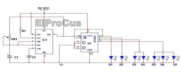
Top 10 Simple Electronic Projects for Beginners in 2014

Austin A30

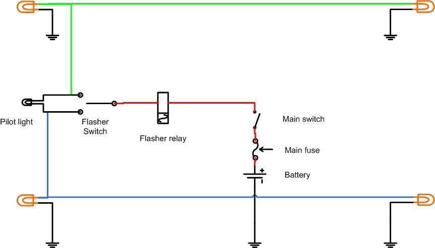
Bicycle Directional Lights - Schematic Design

Light Indicator Wiring Diagrams For 3 Phase Voltage Coming ...

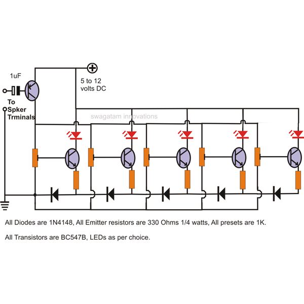
A simple LED lamp circuit from scrap. Uses 5 LED and takes ...

Category Indicators Wiring Diagram

Buy 12V 8mm LED Dash Panel Indicator Light Lamp Red Blue ...
Wiring diagrams | Norton Commando Motorcycle Forum
If you're using a wireless LED dimmer, then you will need to add an LED receiver to. For connecting LEDs first of all it is require to know their connecting points or connection. LED light glow more bright and more looking beautiful than neon bulb.

0 Response to "V Led Indicator Light Wiring Diagram"
Post a Comment