V Rheostat Motor Control Wiring Diagram
V Rheostat Motor Control Wiring Diagram. Speed control of a DC motor is either done manually by the operator or by means of an automatic control device. They're also relatively easy to control, electromechanically using tapped coils, or electronically.
Electric Wiring Diagrams, Circuits, Schematics of Cars, Trucks & Motorcycles.
Control equipment is devices designed to short or open an electrical circuit that may or may not be present in the circuit.

Low voltage DC motor speed control circuit using TDA7274

Phase Controller Wiring / Phase Failure Relay Diagram ...
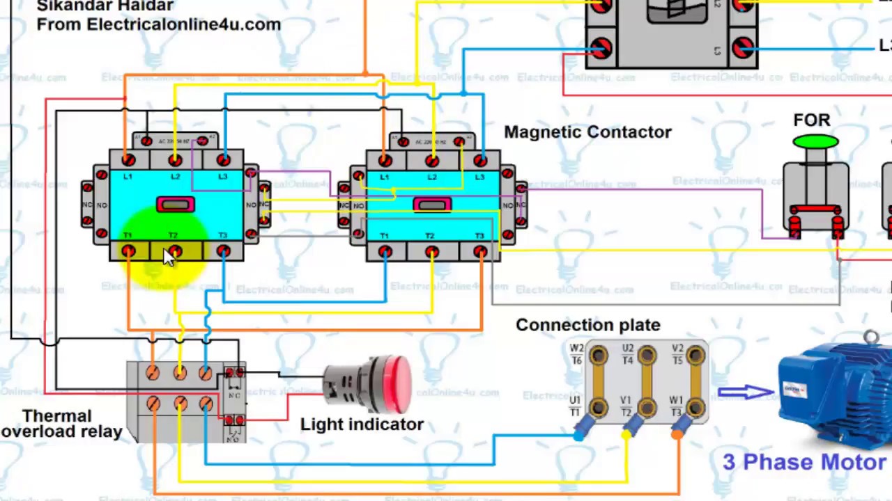
Motor Control Circuit Wiring Instrumentation Tools

Flowchart guide for the Control Circuit of a Direct On ...

PWM 12V dc motor speed controller circuit diagram

Basic Control Circuits
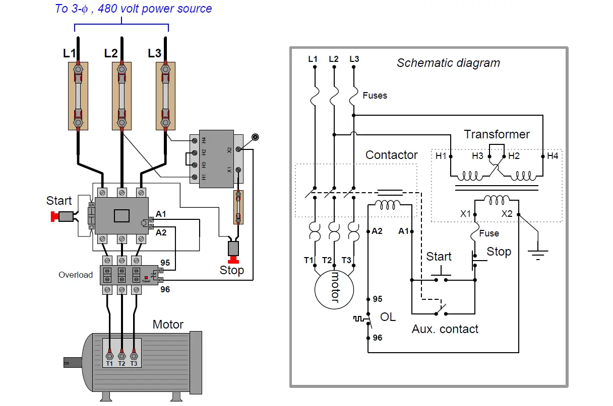
PLC application for reduced voltage-start motor control
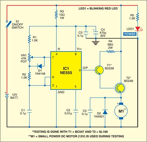
DC Motor Speed Controller | Detailed Circuit Diagram Available
AC motor control circuits : Worksheet
Speed control of a DC motor is either done manually by the operator or by means of an automatic control device. To control the speed of a d.c. motor we need a variable voltage d.c. power source. More precise motor speed control can be accomplished using a vector drive, which uses feedback to modify the PWM output of the VFD.

0 Response to "V Rheostat Motor Control Wiring Diagram"
Post a Comment