V Relay Wiring To Terminal Block Diagram
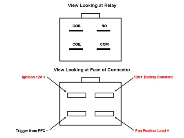
V Relay Wiring To Terminal Block Diagram. How they work, why they're used and some example applications. The diagram shows how the wiring works.

And usually there is a Terminal Block Overview which would look similar Which depicts a three level terminal block, and the wires (cables) connected on each side, and where those cable go.
EE Front left side of fender apron.

12 Volt Rocker Switch Wiring 4 Pin - Amazon Com 4 Pin ...

Flexible Wire-saving System S-LINK V Order guide ...

Can get me the wiring diagram of the IP relay block of my ...

A Low Cost Motor Driver

Fuse Block and Relay Installation | Car fuses, Motorcycle ...
12v 4 Pin Relay Wiring

4PDT 48VDC 5A 14 Pin Terminals Relay Technical Data

3 Pin Flasher Relay Wiring Diagram | Fuse Box And Wiring ...

Automotive Relay Socket with 5 Pin Relay Harness | MGI ...
The image shows a typical PIR sensor pinout diagram. What is a Relay and How Does it Work? We have three channels per relay broken out to blue screw pin terminals.

0 Response to "V Relay Wiring To Terminal Block Diagram"
Post a Comment