V Flasher Wiring Diagram
V Flasher Wiring Diagram. A bulb flasher circuit is very common circuit which most of us come across. Like - Share - Subscribe Support me to make more.

Home » Wiring Diagram » Turn Signal Flasher Wiring Diagram.
An electrical circuit diagram is a graphic representation of special characters and pictograms that are connected in parallel or in series.
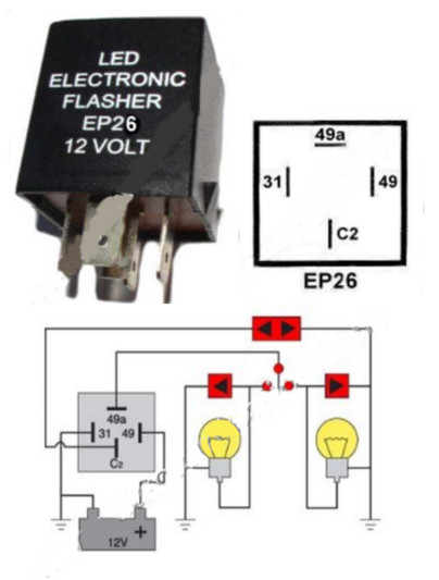
Flasher LED 12V DC 150W 4 Terminal Compatible With EP26 ...

automotive relays 12V 30/40 amp 5 pin SPDT designed
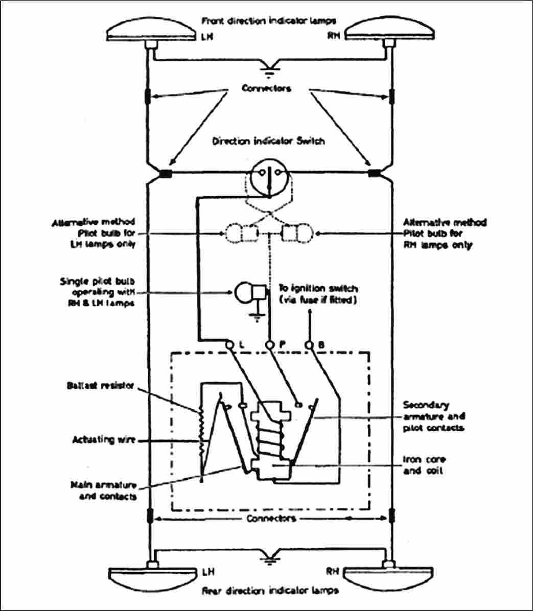
Land Rover FAQ - Repair & Maintenance - Series
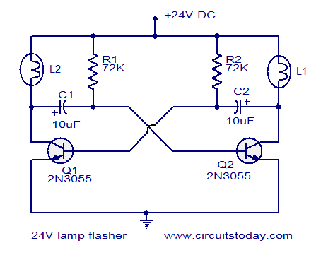
24V flasher circuit

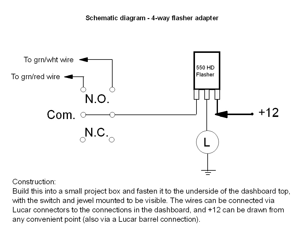
Turn Signal Flasher Wiring Diagram — UNTPIKAPPS

Dorman 5 Pin Relay Wiring Diagram
MODERN FLASHER CIRCUITS

Indicator relay 6V Bosch
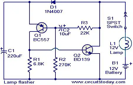
Lamp flasher circuit
Like - Share - Subscribe Support me to make more. Following table shows wire colors related to electrical circuits. Refer to the following manuals for additional service specifications and repair procedures for these models

0 Response to "V Flasher Wiring Diagram"
Post a Comment