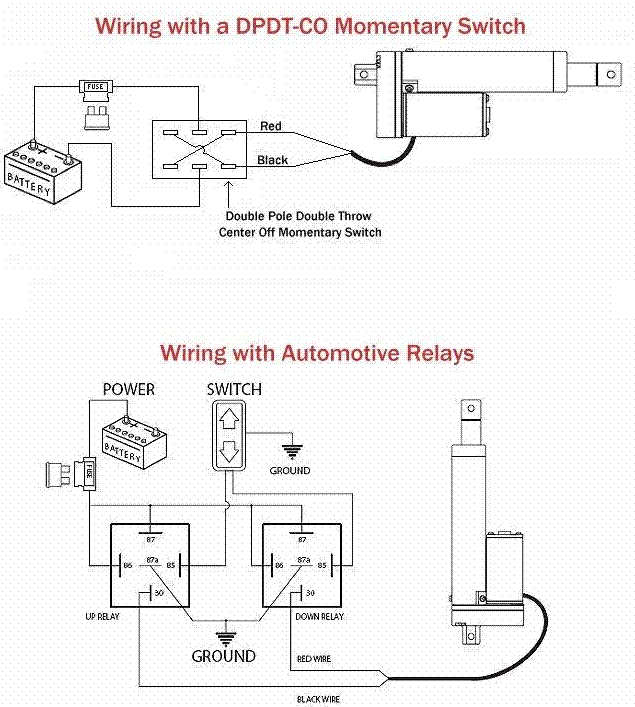
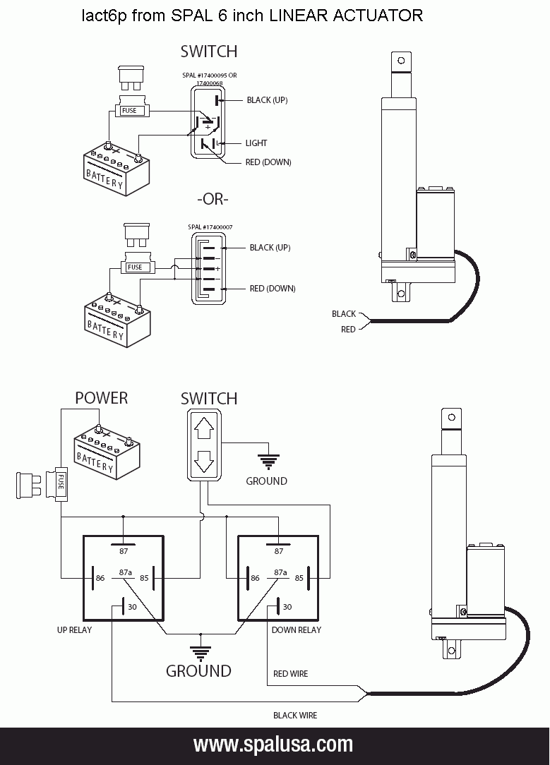
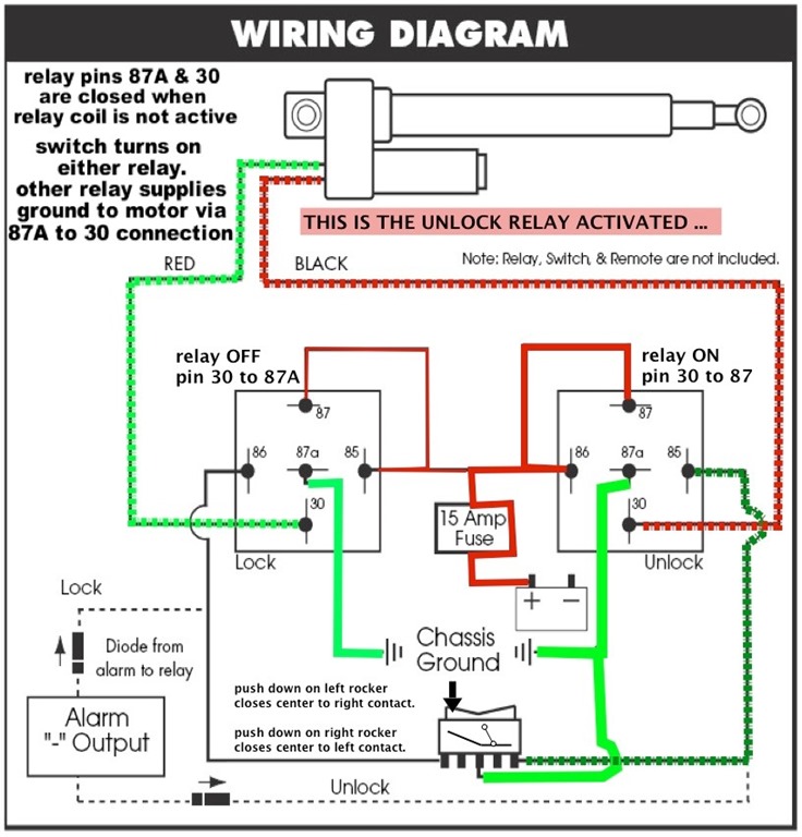
V Linear Actuator Wiring Diagram
V Linear Actuator Wiring Diagram. A wiring diagram is an easy visual representation in the physical connections and physical layout of the electrical system or circuit. However, the power supply and wiring that supply the actuator must be able to handle the motor current for the actuator model and load being used, as well as the inrush current (up to one and a half times the max. continuous current.

The linear actuators in this catalog represent proven design concepts found in the entire Electrak series.
Linear actuators are a type of actuator that convert rotational motion in motors into linear or straight push/pull movements.
They are also useful for making repairs. Today we are going to show you how to connect our linear actuator to our remote controller, and how it's working. However, the power supply and wiring that supply the actuator must be able to handle the motor current for the actuator model and load being used, as well as the inrush current (up to one and a half times the max. continuous current.


0 Response to "V Linear Actuator Wiring Diagram"
Post a Comment